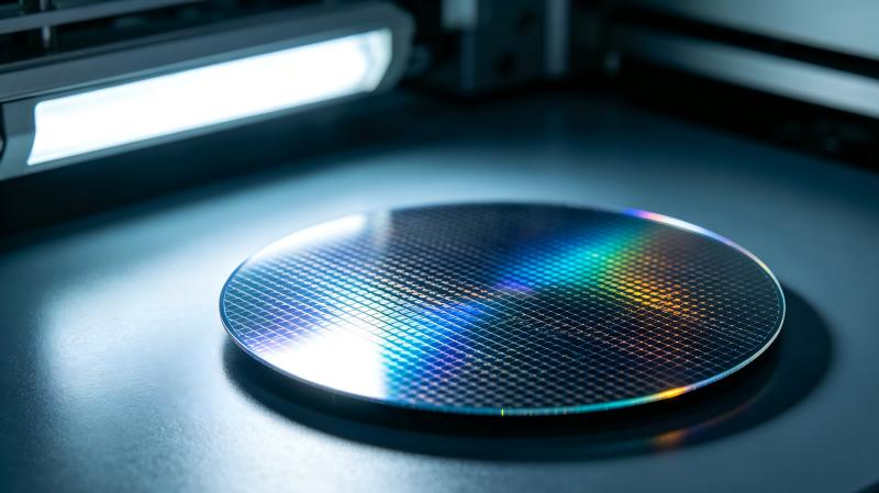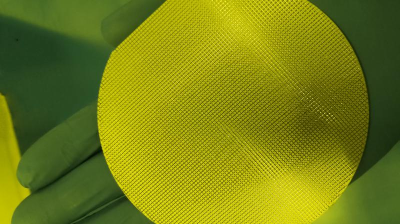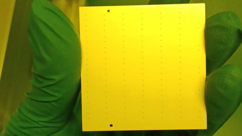
Ultrasonic Photoresist Spray Coating Equipment for 510 × 515 mm Glass Substrates
Coating photoresist on a 510 × 515 mm rectangular glass substrate requires coordinated control of atomization, motion, airflow, solvent evaporation, cleanliness, and lithographic performance. This technical guide describes an evidence-based equipment specification and a qualification workflow for research and manufacturing teams.
Why rectangular glass changes the coating problem
A 510 × 515 mm glass panel is not a scaled-up circular wafer. Its corners, edge exclusion zones, support points, and long travel distances create a different deposition problem. In photomask fabrication, optical devices, microfluidics, MEMS, and display research, the coating process must preserve cleanliness while delivering reproducible film thickness across a large rectangular field. The engineering objective should therefore be expressed as a specification: dry-film thickness, spatial nonuniformity, allowable defect density, edge profile, adhesion, residual solvent, and lithographic critical-dimension performance. A smooth-looking film alone is not evidence that a photoresist process is qualified.
Spin coating versus ultrasonic spraying
Spin coating remains a mature reference method for many flat substrates because centrifugal spreading can produce excellent films within a qualified process window. However, resist dispensed onto a rotating substrate is frequently lost to the bowl and waste stream; the exact fraction depends on dispense volume, geometry, and recovery arrangements. Large rectangular glass also introduces mechanical handling, edge accumulation, corner effects, and balance constraints. Ultrasonic spraying uses a vibrating atomizing surface to create droplets that are directed by a low-pressure carrier gas and deposited by programmed scanning. This avoids high-speed substrate rotation and makes selective coating and multilayer deposition possible. It does not automatically guarantee lower particles, superior uniformity, or a particular utilization percentage: these outcomes must be measured for the selected chemistry and equipment.
Defining the photoresist formulation
The first engineering input is the actual resist grade, not merely the label ‘positive’ or ‘negative’. Record the manufacturer, solvent system, solids fraction, viscosity at a defined temperature and shear condition, surface tension, density, filtration rating, storage requirements, and photosensitivity. Viscosity can vary dramatically between thin imaging resists and high-build formulations. A formulation that atomizes readily may still dry too quickly in flight or produce poor substrate wetting. Confirm whether dilution is permitted by the resist supplier; dilution changes solids content, solvent balance, exposure response, and eventual dry thickness. Conduct compatibility checks on tubing, seals, fittings, and filters using the real formulation rather than assuming that all photoresists behave like PGMEA solutions.
Equipment architecture for 510 × 515 mm panels
The machine requires usable X–Y travel beyond the nominal substrate dimensions to accommodate acceleration, deceleration, edge exclusion, and nozzle overscan. A rigid, low-vibration motion stage, repeatable Z positioning, and a flat or mapped substrate support are essential. Consider a vacuum chuck only when its contact pattern and cleanliness are compatible with the glass and its coatings. The process enclosure should provide light control, filtered make-up air, and predictable exhaust flow. Exhaust capture must remove solvent vapor without creating a lateral draft that distorts the plume. A practical specification includes panel loading repeatability, positioning accuracy, traverse speed stability, nozzle-to-substrate distance, enclosure cleanliness, and maintenance access.
Atomization and droplet transport
Ultrasonic frequency, delivered liquid flow, liquid properties, and nozzle geometry jointly determine the atomization regime. A nominal frequency by itself does not define the droplet-size distribution, and the frequently quoted inverse relationship between frequency and droplet size is only a starting approximation. Verify stable atomization across the intended flow range. Carrier gas should shape and transport the aerosol rather than act as a high-pressure atomizer. Too little gas may yield poor deposition placement; excessive gas can increase overspray, disturb wet films, and entrain contamination. Characterize the actual spray footprint on test coupons and examine whether droplet coalescence produces a continuous wet layer before appreciable solvent evaporation.
Single-nozzle scanning and multi-nozzle arrays
For early process development, a single scanning nozzle provides straightforward experimental control: one flow path, one plume, and a measurable relationship between pitch, traverse speed, and local deposited volume. Its tradeoff is cycle time on a large panel. A multi-nozzle array can improve throughput but introduces nozzle-to-nozzle flow matching, plume interference, overlap calibration, and additional cleaning burden. Evaluate the array only after the single-nozzle process establishes a stable baseline. For either architecture, include lead-in and lead-out travel outside the product area, and measure the effect of scan direction reversals on local film thickness.
A mass-balance starting point
A useful first estimate begins with dry film volume: target dry thickness multiplied by coated area, corrected for edge exclusion and pattern coverage. Convert dry-film volume to dry mass using an appropriate density, then divide by the formulation solids mass fraction to estimate required wet resist mass. The deposited amount must also account for transfer efficiency, which should be determined experimentally by weighing dispensed liquid, collected overspray, and deposited coating where practical. This calculation is a starting point, not a substitute for calibration: solvent loss during flight, wet-film flow, and baking shrinkage all influence the relationship between commanded flow and final thickness.
Scanning pitch, overlap, and pass strategy
A raster scan creates adjacent deposition tracks. If the track pitch is too large, the film develops stripes; if it is too small, excessive local wet loading can generate ridges or solvent entrapment. Establish a track-width profile at a controlled flow, speed, nozzle height, and carrier-gas setting, then select overlap from measured thickness profiles rather than from a generic percentage. For thicker coatings, multiple light passes can be more stable than one heavily loaded pass, provided the interval between passes allows controlled relaxation and solvent evolution. Compare unidirectional and bidirectional rastering because acceleration, plume asymmetry, and edge dwell can produce directional artifacts.
Substrate temperature and solvent management
The thermal state of a glass panel affects wetting, evaporation, and leveling. A warm substrate may reduce spreading time but can also cause droplets to partially dry before coalescence, creating roughness or a powdery surface. A cool substrate may improve wet merging yet promote excessive flow, edge accumulation, or long solvent retention. Temperature should be mapped across the full 510 × 515 mm area, not measured at a single point. Control enclosure temperature, relative humidity where relevant, make-up air, and solvent exhaust consistently. For flammable solvent systems, ventilation, electrical classification, and operating safeguards must follow the facility’s chemical-safety assessment.
Contamination and photosensitivity controls
Particle management requires a system approach: filtered resist, compatible wetted materials, clean fluid connections, controlled loading, and a documented nozzle-cleaning protocol. An ultrasonic nozzle is not inherently particle-free. Dried deposits at the tip, incompatible seals, poor filtration, and contaminated carrier gas can create defects. Minimize stray illumination at wavelengths that activate the photoresist, including during loading, inspection, and maintenance. Validate any automated purge or rinse cycle against the chemistry; a solvent rinse that leaves residues can be worse than a properly managed dry pause. Use witness substrates and particle monitoring to separate incoming glass defects from coating-generated defects.
Metrology for film thickness and edge bead
Measure film thickness at a defined grid of locations spanning center, mid-field, corners, and the intended edge exclusion. Report the number of points, measurement method, mean thickness, minimum, maximum, and relative standard deviation, with RSD defined as standard deviation divided by mean times 100 percent. State whether the edge exclusion region is included. Optical reflectometry or ellipsometry may be appropriate for transparent films if the optical model is valid; stylus profilometry or other methods can provide complementary checks. Inspect edge profiles separately because a favorable central RSD can conceal edge beads, corner accumulation, and incomplete coverage.
Lithography qualification beyond thickness
A resist film must survive its complete downstream process. After coating, apply the supplier-qualified soft bake or a carefully designed bake study, then assess residual solvent and film integrity. Perform exposure and development using the target pattern geometry, measuring critical-dimension uniformity, pinholes, scumming, line breaks, adhesion loss, and pattern collapse where relevant. Compare results with a spin-coated or slot-coated control prepared from the same resist lot and substrate cleaning procedure. A lower coating consumption rate has limited value if defectivity or lithographic yield worsens. Include sufficient replicates to distinguish systematic effects from panel-to-panel variation.
A practical design-of-experiments plan
Begin with a screening study of liquid flow, scan speed, nozzle height, carrier-gas flow, substrate temperature, and track overlap. Keep resist lot, filtration, substrate preparation, ambient conditions, and bake recipe fixed during screening. Randomize run order when practical and include repeated center points to estimate drift. Once dominant factors are identified, use a smaller response-surface study to optimize thickness RSD, edge profile, roughness, and defects together. Do not optimize thickness alone: a recipe that meets average thickness but creates pinholes or poor developed patterns is not qualified. Record nozzle condition and elapsed time since cleaning as potential nuisance variables.
Transfer efficiency and operational cost
Material utilization should be defined consistently as useful coating material retained on the intended area divided by material dispensed. Some ultrasonic systems can achieve high transfer efficiency, but figures such as greater than 70 percent should be treated as application-dependent targets rather than guaranteed specifications. Include priming, purge, cleaning solvent, filters, downtime, and scrap in cost comparisons. A meaningful economic analysis reports both resist consumption per acceptable panel and cost per lithographically qualified panel. For low-volume research, flexibility and reduced changeover effort may be more important than peak throughput; for production, cycle time and reproducibility become central.
Qualification checklist and next steps
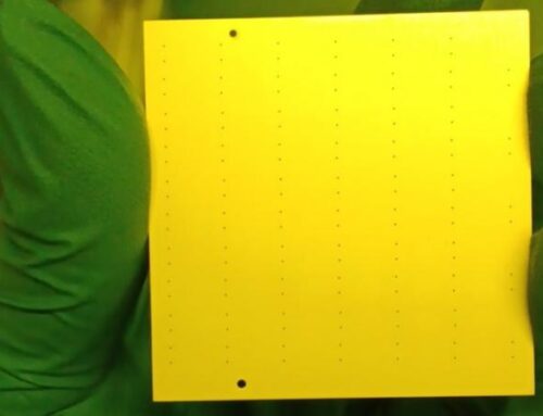
Before selecting equipment, supply the resist technical data sheet and safety data sheet, positive or negative tone, solids and viscosity, intended wet and dry thickness, panel dimensions and flatness, coating edge exclusion, desired RSD, particle criteria, exposure wavelength, minimum critical dimension, bake conditions, and expected daily throughput. Ask the equipment supplier to document a feasibility plan with measurable acceptance criteria and representative coupons or full-size panels. A credible result should include thickness maps, defect inspection, process settings, and downstream lithography outcomes, not only photographs of the sprayed surface. Manufacturers and research teams developing functional coatings on large glass substrates can contact Cheersonic to discuss their application and arrange a coating sample trial.
Explore coating equipment options
For equipment configurations and application discussions, review Cheersonic ultrasonic coating equipment solutions. Contact Cheersonic with your resist data and target acceptance criteria to discuss feasibility and arrange representative coating sample tests.