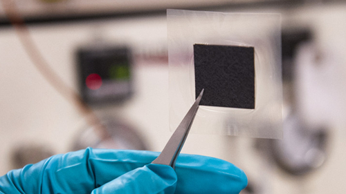
MEA Fabricated by Ultrasonic Spray
Due to the high-quality power, scalability, and fast start-up, proton exchange membrane fuel cells (PEMFCs) are a promising future power source. Membrane electrode assemblies (MEAs) play an important role in performance. A MEA is a composite of a GDL, catalyst layer (CL), and proton exchange membrane (PEM). The electrochemical reaction occurs at the CL. The electrochemical reaction needs a three-phase boundary (TPB) where the catalytic electrode, electrolyte, and gas are all in physical contact. The amount of TPB strongly affects the fuel cell performance. The formula of the catalyst ink dominates not only the fuel cell performance but also the cost. For mass production, the catalyst ink cost is approximately 34% of the total stack cost.

Typically, catalyst ink includes catalyst support, ionomer, solvent, and additive (PTFE, pore former, etc.). Generally, a MEA can be prepared by the three following methods: (i) Catalyst coated membrane (CCM), which is coating CL onto a membrane directly, (ii) Decal transfer CCM, which is coating CL on a substrate and then transferring the CL onto a membrane, and (iii) Catalyst coated substrate (CCS), which is coating CL on GDL (a GDL with CL is called a gas diffusion electrode (GDE)). A MEA is fabricated by sandwiching a CCM between two GDLs, or sandwiching a PEM between two GDEs.
MEAs fabricated by CCM offered better performance than CCS. The CCM delivers lower resistance than CCS due to improved CL membrane ionic contact, regardless of if the CCM is spray or electrospray coated. The CCM also showed better durability than CCS. Millington et al. investigated four different solvents for producing catalyst inks; the solvents were tetrahydrofuran (THF), iso-propanol (IPA), ethylene glycol (EG) and glycerol. Due to its low dielectric constant, THF showed better performance than IPA as the solvent in the catalyst inks, while EG and glycerol led to poor performance. Song et al. investigated the effect of PTFE content in the CL; results indicated that adding certain PTFEs could improve the concentration polarization of the CL. The optimal PTFE content was 5 wt%, which did not affect the charge transfer resistance but improved the internal mass diffusion of the CL. Pore former can modify the pore volume. The optimal pore former content is 30 wt%, but it led to lower durability.
There are many coating techniques for fabricating a CL, such as sputter deposition, ion-beam assisted deposition, doctor blade, screen printing, inkjet printing, spraying, electrospraying, and ultrasonic spraying. Chaparro et al. reported that for an electrospraying process, the optimum Pt loading (cathode) and Nafion content ratio were 0.17 mg/cm2 and 17 wt%, respectively. The electrospray process homogeneously covered the ionomer film with the Pt/C agglomerate, forming a highly porous material with lower resistivity. Sasikumar et al. and Martin et al. investigated the optimum Nafion content ratio at various Pt loadings. The results indicated that the optimum Nafion content ratio decreases with increasing Pt loading with CLs coated by either brush or electrospray. The optimum values are significantly different depending on the coating method used. Millington et al. indicated the main problem with the electrospraying technique is that the peak power density value is too low to be used in practical applications. A MEA fabricated by ultrasonic spray demonstrated high performance at low Pt loading. However, Millington et al. fabricated the MEA using the CCS technique and tested with oxygen as the oxidant and under high back pressure. The CCM technique was used and investigated with air oxidant and at ambient pressure; this approach is more consistent with real applications. In addition, it is the first study to use ultrasonic spray for investigating Pt loading using the CCM technique.

