
Hydrogen Fuel Cell Engine Stack MEA Gas Diffusion Layer
We come to another key component of the hydrogen fuel cell engine stack – the Gas Diffusion Layer (GDL). It is located between the membrane electrode (MEA) and the bipolar plate. Although its structure is relatively simple, its function is crucial and it is the core that affects the hydrothermal management and performance stability of the fuel cell stack.
The role and importance of gas diffusion layer (GDL)
GDL is a porous, conductive thin layer material, whose main functions can be summarized as:
1. Gas Diffusion Transport:
Spread the reaction gases (H ₂ at the anode and O ₂/air at the cathode) uniformly from the flow channels of the bipolar plate to the entire reaction area of the catalyst layer (CL).
This is its most basic function, therefore it is required to have high porosity and suitable pore structure.
2. Electrical conduction:
As a conductor, it efficiently conducts the electrons generated by the reaction in the catalyst layer to the bipolar plate, forming a current circuit.
Therefore, it is required to have high electronic conductivity and low contact resistance.

3. Water Management – This is its most core and complex function:
- Discharge generated water: At the cathode, oxygen reduction reaction generates water. GDL must be able to effectively drain this water to prevent flooding. If water cannot be discharged, it will block the pores, hinder gas transmission to the catalyst layer, resulting in “mass transfer loss” and a sharp decline in performance.
- Maintain appropriate humidity: At the same time, it also needs to help maintain sufficient wetting of the proton exchange membrane (PEM) to prevent the membrane from becoming too dry and causing a decrease in proton conductivity.
- This delicate balance is achieved through the hydrophobic treatment and pore structure of GDL.
4. Thermal Management:
Fuel cell reactions generate heat. The thermal conductivity of GDL helps to transfer heat from the catalyst layer to the bipolar plate, which is then carried away by the cooling channels of the bipolar plate, maintaining stable operating temperature of the fuel cell stack.
5. Mechanical Support:
Provide mechanical support for fragile membrane electrodes, especially thin as cicada wings proton exchange membranes and catalyst layers, and buffer pressure during stack compression to prevent MEA from being crushed.
Structure and Composition of Gas Diffusion Layer (GDL)
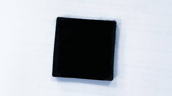
Usually, GDL consists of two parts: a substrate/backing layer and a microporous layer (MPL).
1. Substrate
- Material: Usually carbon fiber paper or carbon fiber cloth. Carbon fiber paper is more widely used in commercial fuel cells due to its more uniform structure and lower cost.
- Manufacturing process: Polyacrylonitrile (PAN) – based carbon fibers are made into paper like materials through a papermaking process, and then subjected to high-temperature graphitization treatment to give them a stable structure, excellent conductivity, and corrosion resistance.
- Characteristic:
– Thickness: typically 150-400 microns.
– High porosity: usually>70%, providing macroscopic transport channels for gas and water.
– Has a certain degree of rigidity: provides mechanical support.
2. Microporous Layer (MPL)
- Location: A thin coating applied between the substrate layer and the catalyst layer.
- Material: Composed of a mixture of conductive carbon powder (such as acetylene black, carbon black) and hydrophobic agent (usually polytetrafluoroethylene, PTFE).
- Characteristic:
– Thickness: about 30-50 microns.
– Smaller pore size: Compared to the substrate layer, the pores of MPL are at the nanometer/micrometer level, forming a more refined pore structure. - Core functions:
– Improve interface contact: provide a smoother surface, form closer contact with the catalyst layer, and significantly reduce contact resistance.
– Enhancing water management capabilities: This is the most critical role of MPL. Its fine pore structure can generate enormous capillary force, which helps to “suck” the liquid water generated in the catalyst layer into the coarse pores of the substrate layer and then discharge it. At the same time, the hydrophobicity of PTFE prevents excessive water reflux, effectively avoiding cathode “flooding”, especially during high current density operation.
– Protect CL: prevent catalyst particles from penetrating into the porous substrate layer and causing losses.
Key characteristic parameters of GDL
Porosity and pore size distribution: affecting the transport capacity of gases and water.
Breathability: directly measures the ease of gas passing through GDL.
Hydrophilicity/hydrophobicity: mainly determined by the content of PTFE, it is the core of water management ability. GDL is usually hydrophobic.
Through Plane Resistance: includes the resistance of the material itself and the contact resistance with CL and BPP, which directly affects the Ohmic loss of the battery.
Thickness: affects the gas diffusion distance, mechanical strength, and volumetric power density of the entire fuel cell stack.
Mechanical strength: Ensure that it is not torn or excessively compressed during assembly and operation.
Development Trends and Challenges
Optimize water management: Develop GDL/MPL with gradient pore structure or gradient hydrophobicity to more finely control water transport and distribution, further enhancing performance at high current densities.
Thinning: In order to improve the volumetric power density and mass power density of the fuel cell stack, a thinner GDL with unaffected mechanical strength and functionality is developed.
Enhanced durability: Under fuel cell start stop conditions, a high potential (>1.5V) is generated on the cathode side, leading to corrosion of carbon materials. Developing corrosion-resistant GDL (such as using carbon fibers with higher degree of graphitization or surface modification) is the key to improving its lifespan.
Cost reduction: The cost of GDL accounts for about 10% -15% of the fuel cell stack. Further reduce costs through large-scale production and process optimization.
In summary, the gas diffusion layer is much more than just a simple “diffusion” material. It is a complex porous medium with the core mission of efficiently managing the transport and balance of four substances: gas, liquid, electricity, and heat. The quality of its performance directly determines the performance and stability of fuel cells, especially under harsh operating conditions.
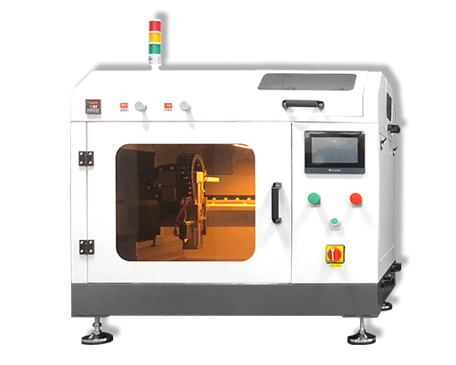
The gas diffusion layer of fuel cells is a key component that ensures efficient electrochemical reactions, requiring excellent breathability, conductivity, and corrosion resistance. Ultrasonic spraying machines, with their precise coating ability, have become the core equipment for coating preparation. During operation, the ultrasonic generator converts high-frequency electric energy into mechanical vibration, which is transmitted to the nozzle through the transducer, so that the slurry mixed with carbon powder and PTFE lotion is atomized into uniform droplets with a diameter of 5-10 microns, avoiding the problem of agglomeration of droplets in traditional spraying.
During the coating process, the sprayer moves along a preset path, with the nozzle maintaining a constant distance of 15-20 centimeters from the gas diffusion layer substrate. Combined with an atomization pressure of 0.1-0.3 MPa, the droplets are evenly deposited on the substrate surface to form a coating with a thickness of 5-20 microns. Subsequently, after hot air drying at 80-120 ℃ and high-temperature sintering at 300-350 ℃, the coating is tightly bonded to the substrate. This coating method not only controls the porosity of the coating within the ideal range of 70% -80%, improves mass transfer efficiency, but also reduces slurry waste, with a material utilization rate of over 90%, laying the foundation for the long life and high power output of fuel cells.
About Cheersonic
Cheersonic is the leading developer and manufacturer of ultrasonic coating systems for applying precise, thin film coatings to protect, strengthen or smooth surfaces on parts and components for the microelectronics/electronics, alternative energy, medical and industrial markets, including specialized glass applications in construction and automotive.
Our coating solutions are environmentally-friendly, efficient and highly reliable, and enable dramatic reductions in overspray, savings in raw material, water and energy usage and provide improved process repeatability, transfer efficiency, high uniformity and reduced emissions.
Chinese Website: Cheersonic Provides Professional Coating Solutions
