
The Production Process of Hydrogen Fuel Cell Engines
A hydrogen fuel cell engine is more like an integrated power generation system, with the fuel cell stack as its core.
Core Processes and Key Technologies:
Core Components – Stack Manufacturing
- Bipolar Plates: Typically made from graphite or metal plates (such as stainless steel or titanium alloy) through precision stamping or milling, the surface requires a coating (such as gold or carbon) to prevent corrosion and reduce contact resistance. Flow channel design is crucial, ensuring uniform distribution of hydrogen and air.
- Membrane Electrode Assembly (MEA): This is the “heart” of the stack and consists of three parts:
– Proton Exchange Membrane (PEM): Typically DuPont’s Nafion membrane, a solid electrolyte that only allows protons (H⁺) to pass through.
– Catalyst Layer: Coated on both sides of the membrane, it is typically platinum (Pt) or platinum alloy nanoparticles that accelerate the hydrogen oxidation and oxygen reduction reactions. – – Gas Diffusion Layer (GDL): Typically made of carbon paper or carbon cloth, it features a porous structure that evenly transports gas and conducts water and electrons. - Stacking and Packaging: Hundreds of bipolar plates and MEAs are alternately stacked and secured with end plates and high-strength bolts to form a compact stack, ensuring a tight seal at all locations to prevent cross-flow.

Manufacturing and Integration of Auxiliary Systems (BOP – Balance of Plant)
- Air Supply System: Includes air filters, an air compressor (provides oxygen for the oxidation reaction), and a humidifier (humidifies the air entering the fuel cell stack to prevent drying of the proton exchange membrane).
- Hydrogen Supply System: Includes a high-pressure hydrogen tank, a pressure reducing valve, a circulation pump/ejector (utilizes unreacted hydrogen in the fuel cell exhaust to improve efficiency), and an exhaust valve (regularly removes accumulated nitrogen and water).
- Thermal Management System: Includes a coolant pump, radiator, thermostat, and deionizer (the coolant must be deionized water to prevent conductivity). Fuel cells have an efficiency of approximately 50%, with the remaining energy dissipated as heat, requiring efficient heat dissipation.
- DC-DC Converter: Boosts the fluctuating DC power generated by the fuel cell to the required voltage.
Complete Assembly and Testing
- System Integration: All components of the fuel cell stack and BOP are integrated into a single chassis using piping, wiring harnesses, and brackets to form a complete fuel cell engine module.
- Control System Development: Developing a fuel cell control unit (FCU) monitors stack voltage, temperature, pressure, and other parameters in real time, intelligently adjusting the air compressor, water pump, hydrogen valve, and other components to ensure efficient and safe system operation, especially under cold start and variable load conditions.
- Comprehensive Testing: Conducting performance tests (efficiency, power response), life tests (attenuation rate), environmental adaptability tests (high and low temperature, high altitude), and safety tests (hydrogen leakage, electrical safety).
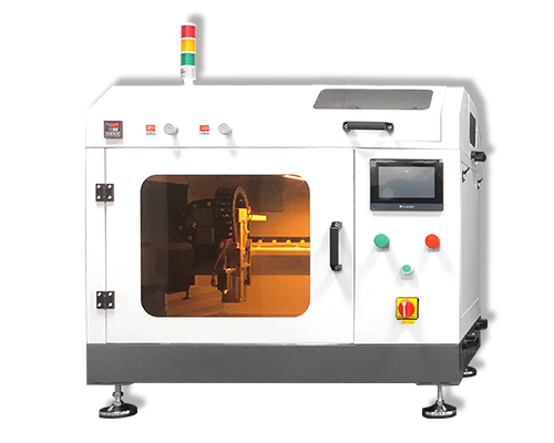
Ultrasonic spraying machines have outstanding advantages in spraying membrane electrode catalyst layers and are a key technology for the preparation of core components of fuel cells. They use high-frequency vibrations to atomize the catalyst slurry into uniform droplets of 5-20 microns, which can form a dense catalytic layer without pinholes and agglomeration on the surface of the proton exchange membrane, ensuring that the active sites are fully exposed and improving the catalytic efficiency. The coating thickness is precisely controllable (0.1-5 microns) to adapt to different power requirements. The material utilization rate exceeds 90%, which greatly reduces the waste of precious metals such as platinum and reduces costs. There is no high-speed airflow impact during spraying, which avoids membrane damage and catalyst particle agglomeration. The process is highly stable and can improve the conductivity and durability of the membrane electrode, helping fuel cells achieve high power density and long life.
About Cheersonic
Cheersonic is the leading developer and manufacturer of ultrasonic coating systems for applying precise, thin film coatings to protect, strengthen or smooth surfaces on parts and components for the microelectronics/electronics, alternative energy, medical and industrial markets, including specialized glass applications in construction and automotive.
Our coating solutions are environmentally-friendly, efficient and highly reliable, and enable dramatic reductions in overspray, savings in raw material, water and energy usage and provide improved process repeatability, transfer efficiency, high uniformity and reduced emissions.
Chinese Website: Cheersonic Provides Professional Coating Solutions
