
PEM Electrolytic Electrolyzers Testing Issues
Many practitioners often encounter situations where the performance of proton exchange membrane (PEM) electrolyzers does not meet expectations when testing, but it is difficult to pinpoint the root cause of the problem. There are many factors that affect test performance, including catalyst characteristics, slurry dispersion effect, spraying process parameters, catalyst loading, proton membrane selection, sealing gasket matching, and assembly torque. Among them, the membrane electrode preparation process is the core influencing factor. Before troubleshooting, reference standards need to be established, and typical parameters of commercial PEM electrolyzers can be used as benchmarks: the anode uses iridium oxide (IrO ₂) catalyst, the cathode uses platinum carbon (Pt/C) catalyst, and the catalyst to proton membrane solvent ratio is 0.8~1; After dispersing the slurry through probe ultrasound and homogenizer, the catalyst is loaded onto a proton membrane (CCM structure) using electrostatic spraying, ultrasound spraying, two fluid spraying, or roll to roll process. The anode loading is usually 1.0-1.5mg/cm ², and the cathode loading is 0.2-0.4mg/cm ²; Proton membranes can be selected from domestic models or imported 115/117 series. The anode gas diffusion layer is coated with platinum titanium felt, and the cathode can be coated with platinum titanium felt or carbon paper; The assembly torque should be ≥ 6N, pure water should be used for liquid inlet, and the flow rate should not be less than 20mL/(min · cm ²) calculated based on the effective area. The test temperature should be controlled at 80 ℃. Under these conditions, the performance of the membrane electrode can usually be maintained at a level of 2A/cm ² @ 2V.
The typical testing conditions for commercial electrolytic cells can refer to: anode IrO ₂ loading capacity of 1.0mg/cm ², cathode Pt/C loading capacity of 0.2mg/cm ², proton exchange membrane selection of 115 series, catalyst effective area of 1cm ² or 25cm ², and both anode and cathode diffusion layers are coated with platinum titanium felt; The test temperature is 80 ℃, the conductivity of the circulating water is less than 5 μ S/cm ², the flow rate corresponding to a 4cm ² area is 200mL/min, and the flow rate corresponding to a 25cm ² area is 1.0L/min. By comparing the above parameters, the reasons for poor performance of the electrolytic cell can be investigated item by item:
Catalyst performance investigation
The independently synthesized anode acid oxygen evolution reaction (OER) material needs to be screened through a three electrode system test before assembling the membrane electrode (MEA). If the performance and stability of the material are better than commercial IrO ₂ in the three electrode test, then assembly usually achieves better results; If the performance after assembly is lower than the commercial level, it is likely that there are problems in the membrane electrode preparation process. It is possible to try using commercial IrO ₂ material replication testing to verify whether it can meet commercial standards and eliminate the influence of the catalyst itself.

Handling of slurry dispersion problem
The slurry problem mainly stems from insufficient dispersion. If the self synthesized catalyst has a large particle size, it is prone to settling and difficult to achieve uniform dispersion, which can lead to poor spraying effect, low material specific surface area, rapid performance degradation, easy catalyst detachment, and even clogging of the spray nozzle. The dispersion effect can be improved by extending the ultrasound time, but the fundamental solution is to reduce the material particle size during the synthesis stage and improve dispersion from the source.
Optimization of Spray Coating Process
The spraying process is a key factor affecting the performance of membrane electrodes. Manual drip coating or handheld spray gun spraying is difficult to ensure uniformity, and the adhesion between the catalyst and the membrane is poor, which can lead to problems such as detachment and poor mass transfer; If the solvent is not evaporated in time during spraying, it may also cause swelling of the proton membrane, leading to more serious malfunctions. Some practitioners choose to spray the catalyst onto the diffusion layer and then press it onto the membrane. In theory, whether sprayed onto the membrane surface or the diffusion layer, the effect is similar after mechanical tightening or hot pressing. However, in practical applications, due to the more stable bonding between the binder and the proton membrane, which is more conducive to mass transport, the effect of directly spraying the catalyst onto the membrane surface (CCM structure) is better.
For CCS self-supporting electrodes grown in situ on the diffusion layer, there is no need to consider adhesion issues and they can be used directly; However, the powder catalyst needs to be loaded through a spraying process, so the CCM scheme is commonly used in commercial scenarios, using ultrasonic spraying equipment to spray the slurry onto the membrane surface. CCM spraying requires specialized equipment support. If the testing quantity is small, it is more economical to entrust a professional organization to process the membrane electrode than to purchase equipment on your own; If the laboratory has spraying equipment, it is recommended to first use commercial catalysts to prepare membrane electrodes, compare them with commercial test results, verify the process stability, and then test the membrane electrodes made of independent materials.
Catalyst loading control
The relationship between catalyst loading and performance follows a “volcano diagram”: too low a loading can lead to insufficient active sites, affecting performance and stability; If the load is too high, it will hinder mass transfer and also reduce performance. The optimal loading amount for different catalysts varies, and currently the mainstream loading amount for commercial anode IrO ₂ is 1mg/cm ², which can ensure testing stability while controlling costs. Some companies claim to be able to reduce the IrO ₂ loading to 0.4-0.5mg/cm ², and there are also reports of lower loading in the literature. However, low loading membrane electrodes need to undergo long-term stability verification, and durability should not be ignored in pursuit of low loading.
Suggestions for proton membrane selection
The commonly used imported 115/117 series perfluorosulfonic acid proton membranes are currently restricted in domestic procurement channels, and attention should be paid to identifying the authenticity of the products. In recent years, domestic proton membrane technology has developed rapidly, with performance and tolerance approaching that of imported products, and the price is only half of imported membranes, effectively breaking the dependence on imports and solving the technical bottleneck in this field.
Key points for matching sealing gaskets
The thickness of the gasket needs to match the thickness of the diffusion layer, and its size will affect the contact resistance of the electrolytic cell. The matching effect can be analyzed through impedance testing to ensure the compatibility between the gasket and the electrode structure.
Assembly torque adjustment
Even for electrolytic cells of the same model, different assembly torques can affect the test results. The larger the effective area of the membrane electrode, the higher the required torque to ensure the sealing of the electrolytic cell. Usually, the torque needs to be controlled above 6N. If the torque is too small, it will increase the contact resistance, while if it is too large, it may damage the proton membrane or hinder mass transfer in the diffusion layer.
In addition to the above factors, the corrosion resistance of bipolar plates, channel design, and inlet flow rate can also affect performance. If there is a lack of sufficient energy to investigate each item, professional institutions can be commissioned to complete the preparation and assembly testing of membrane electrodes, in order to focus on the research of the materials themselves.
Precautions for the use and storage of membrane electrodes
Even if the preparation of membrane electrodes meets the standard, improper use and storage can lead to performance degradation. The following points should be noted:
- Ready to use and sealed storage: Membrane electrodes are recommended to be prepared and used immediately. If the laboratory has spraying equipment, the unused membrane electrodes prepared in one go need to be vacuum sealed and stored, with a shelf life of more than 3 months; The purchased finished membrane electrodes need to be vacuum sealed and shipped from the supplier, and any unused parts should be stored in a timely vacuum sealed manner.
- Wet storage after use: Used membrane electrodes should be stored in a wet, sealed, and dark condition, and tested again as soon as possible. If the test is suspended and the electrolytic cell is not disassembled, it is necessary to maintain continuous water supply or water injection sealing to ensure that the membrane electrode is always in a moist state – the performance of the proton membrane will rapidly deteriorate after drying and cannot be repaired; If it is necessary to disassemble or replace the membrane electrode, the used membrane electrode should be sealed and stored away from light in a moist state, and retested within one week to avoid performance degradation caused by exposure to air humidity, oxygen, or light.
- Water supply and temperature control during testing: The electrolytic cell needs to be supplied with water before electricity to prevent dry burning and damage to the proton membrane. Temperature controlled electrolytic cells with heating rods or plates should be slowly heated from room temperature to the target temperature to avoid setting high temperatures directly, which can cause excessive instantaneous power and irreversible damage to the membrane electrode; If the electrolyte is heated and controlled by a water bath, it can be introduced into the electrolytic cell after the electrolyte temperature stabilizes. At the same time, temperature monitoring and insulation of the electrolytic cell should be done well.
- Electrochemical activation: The prepared membrane electrode does not require water immersion activation, but the catalyst needs to be electrochemically activated – run at constant voltage for a period of time under the condition of current density ≤ 1A/cm ² (or voltage ≤ 1.8V, it is recommended to use 1.6-1.7V), and test normally after the current stabilizes. As long as the performance is not degraded, the prepared membrane electrode can be used continuously without frequent replacement.
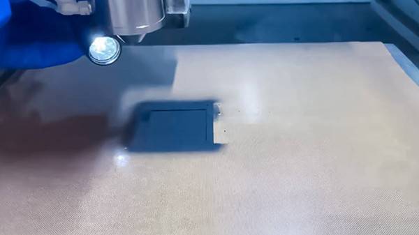
Ultrasonic spraying is an advanced process for preparing catalyst coatings for PEM electrolysis cells. It uses ultrasonic vibration (usually 20-180kHz) to atomize the catalyst slurry into micrometer sized uniform droplets, which are accurately deposited on the surface of proton exchange membranes or gas diffusion layers. Compared to traditional spraying, this technology has significant advantages: controllable atomization particle size (5-50 μ m), coating thickness uniformity error<5%, and can reduce the amount of precious metal catalysts such as Pt and Ir by more than 30%, reducing costs while improving utilization.
In the process, parameters such as slurry concentration, ultrasonic power, and spraying speed need to be precisely controlled: low concentration slurry is suitable for high ultrasonic power, which can form porous structural coatings and optimize gas-liquid transmission channels; Moderate spraying speed (5-15mm/s) can avoid droplet accumulation or missed coating. The prepared coating has strong adhesion (peel strength>1.2MPa) and a micro porosity of 40% -60%, which is suitable for high current density conditions (1-2A/cm ²) of PEM electrolysis cells. It can improve electrolysis efficiency to over 85% and extend the life of membrane electrode assembly (MEA) to over 10000h, providing key technical support for the large-scale production of green hydrogen.
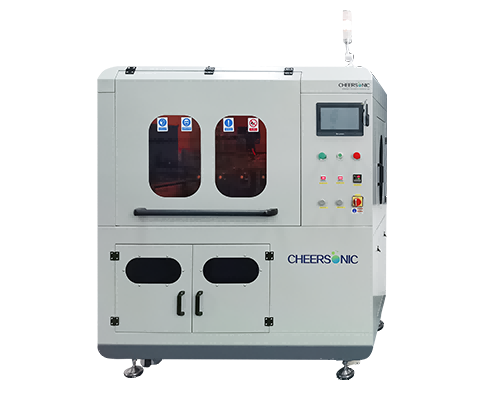
About Cheersonic
Cheersonic is the leading developer and manufacturer of ultrasonic coating systems for applying precise, thin film coatings to protect, strengthen or smooth surfaces on parts and components for the microelectronics/electronics, alternative energy, medical and industrial markets, including specialized glass applications in construction and automotive.
Our coating solutions are environmentally-friendly, efficient and highly reliable, and enable dramatic reductions in overspray, savings in raw material, water and energy usage and provide improved process repeatability, transfer efficiency, high uniformity and reduced emissions.
Chinese Website: Cheersonic Provides Professional Coating Solutions
