
Fuel Cell Bipolar Plate Design Features
Fuel Cell Bipolar Plate Design Features – Fuel Cell Coating – Cheersonic
The bipolar plate is the main structural support of the fuel cell stack, and its structural design forms the flow channels of hydrogen, air and water inside the stack. As the main structural component of the stack, the thickness of the bipolar plate directly affects the power density of the stack. At present, due to the relatively high technical threshold of the membrane electrode in the industry, the breakthrough progress is slow, and the performance improvement of the stack product is still the main force. Concentrate on the bipolar plate.
Fuel cell bipolar plates must meet the following performance requirements:
1. In order to play the role of single battery in series in structure, the bipolar plate must have high conductivity;
2. To isolate the reaction gas and heat dissipation water in each cavity, the gas permeability of the bipolar plate needs to meet the requirements;
3. The heat in the reaction area is quickly transferred to the cooling liquid, and the bipolar plate must have high thermal conductivity;
4. Considering the structural strength, vibration, power density and low temperature start-up, the strength, density and heat capacity of the bipolar plate material should also meet the product performance requirements.
Metal materials have high electrical conductivity and electrical conductivity, high gas barrier rate and material strength, and are suitable for thinner plates, but the materials are easy to corrode and require a special coating process. The graphite plate is relatively thick, but the material is relatively stable and has certain advantages in durability.
1 Meet the active area requirements
The design of the bipolar plate should first consider meeting the active area requirements of the stack power. As shown in the power generation area in the red box on the left side of the figure below, the selection of the active area area is closely related to the position of the uniform gas distribution area and uniform temperature distribution area of the stack. Otherwise, the durability of the stack will be affected. At present, the power demand of fuel cells continues to increase, and the active area of membrane electrodes is increasingly required. When increasing the area, it is necessary to consider whether the molding and stamping processes can meet the processing requirements of large-scale positive plates.
2 Consider all aspects of tolerance
In addition, the dimensional tolerances, geometrical tolerances and assembly tolerances of the bipolar plate, membrane electrode and sealing line should be fully considered in the design of the electrode plate. Only reasonable tolerance design can ensure the reliability, consistency and durability of the product. The following figure shows the mating section of the bipolar plate, the sealing wire and the membrane electrode. The rational design of the mating area has an important impact on the assembly performance, dry and wet durability, and active area ratio.
3 Material properties and molding process
The bipolar plate design process should fully consider the material characteristics and forming process. Compared with the metal plate, the strength of the graphite plate is lower and the gas permeability is higher. Therefore, there must be a safety margin in the thickness of the plate. At present, the graphite plate is generally engraved. Keep at least 0.3mm thickness at the thinnest part, and the thickness of the molded plate material will be thinner. As shown in the figure below, there is a thick material spacing between the bottom of the flow channel of the left graphite plate, while the other side of the hydrogen and air cavity is combined into a water channel when the right metal plate is formed, and the plate is only 0.1mm thick , thinner than a single cell with a graphite bipolar plate.
4 Air distribution port and structural strength design
When designing the inlet at the gas distribution inlet of the electrode plate, the metal plate has the following two methods: one is to have a gas distribution separator between the cathode and the anode plate, and the structure is relatively complex; the other is to form a Z-shaped gas distribution Although the width of the sealing area will be increased, the overall structure is simple.
The graphite bipolar plate uses a perforated method, and uses the anode plate and the cathode plate to form a gas distribution port, and the structure is relatively simple.
The maximum power of the stack needs to have a matching air distribution port design and structural strength design. The area of the air distribution port will affect the upper limit of the number of batteries assembled. The plate structure design affects the strength of the stack in all directions after assembly. In addition, the gas flow direction, the stack Factors such as placement direction, process process hole position, inspection and power supply, and power supply board power supply must be considered in the design stage. Metal bipolar plates from different manufacturers have three-way media inlet and outlet designs on the same side, as well as different designs for other needs.
5 The flow field medium is evenly distributed
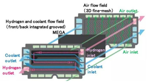
In terms of flow field design, the design of air path, hydrogen path and water path should ensure uniform distribution of medium, and reasonable pressure drop design should ensure uniform distribution among different single cells, especially on the hydrogen and air sides to reduce the influence of liquid water , in the design of the runner, the matched engine system and the corresponding working conditions should also be considered, and the design of each manufacturer is different.
It is believed that with the continuous advancement of fuel cell technology in the future, more innovative designs will emerge.
Our company’s ultrasonic spraying equipment can be sprayed on a variety of different metal alloys, including the preparation of platinum, nickel, iridium and ruthenium-based fuel cell catalyst coatings, as well as PEMs, GDLs, DMFCs (direct methanol fuel cells) and SOFCs (solid Oxide fuel cell) manufacturing. The battery manufactured by this technology has the characteristics of high battery load and high battery efficiency.
