
Do you really know the gas diffusion layer?
Do you really know the gas diffusion layer? Fuel Cell Catalyst Coating – Cheersonic
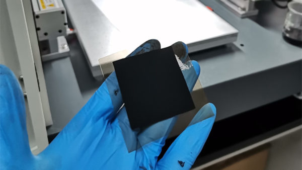
The gas diffusion layer directly connects the fuel cell electrode to the catalytic layer structurally, creating a bridge from the millimetre scale of the gas flow path to the nano-scale of the catalyst, which not only serves to transport the reaction medium and discharge the electrochemical products in the operation of the fuel cell, but also continuously conducts heat and electricity. Depending on the bonding, weaving, paper forming and hot pressing processes used in the production of the gas diffusion layer, the finished product can be divided into carbon paper, carbon cloth, carbon felt and many other types of products.
Gaseous diffusion layer production process
Step 1. Carbonisation of organic fibres
The organic polymer is spun and stabilised and then formed into carbon fibres through high pyrolysis temperatures of up to 1100-1350°C. The pyrolysis takes place in an inert gas, releasing large amounts of hydrogen, nitrogen and oxygen to form carbon fibre products with a carbon mass fraction of over 90%.
Step 2. Paper/woven process
The carbon fibres are sheared in sections and dispersed in a special solution, followed by the forming of the carbon paper in a process similar to paper making.
Step 3. Graphitisation
The graphitisation of the formed GDL is completed by heating to 2200-3000°C. This stage is very important as the diffusion layer will be enhanced in terms of electrical and thermal conductivity and mechanical strength, and the chemical stability and surface physical stability of the diffusion layer will be enhanced.
Step 4. hydrophobic treatment
This stage involves the impregnation, drying and sintering of the PTFE solution. The hydrophobic treatment of the diffusion layer plays an important role in the smooth drainage of the water generated during the fuel cell operation without hindering the diffusion of the reaction gases, as the GDL is less hydrophobic than the MPL layer, creating a hydraulic gradient to prevent flooding.
Step 5. MPL layer coating
Finally, the MPL layer emulsion is applied to the GDL layer by spraying, silk-screening or deposition, and finally sintered to form the gas diffusion layer.
Gas diffusion layer properties
The selection of the gas diffusion layer has a significant impact on the fuel cell performance in the fuel cell stack design process, and is usually based on a comprehensive consideration of thickness, specific gravity, compression rebound, thickness, porosity, PTFE content, electrical conductivity properties, thermal conductivity properties and gas diffusion properties.
1. Mechanical properties
The strain, porosity, conductivity and gas diffusion characteristics of the diffusion layer will change as the compression force increases during the stack assembly process. The resilience of the diffusion layer, the matching of the diffusion layer to the sealing line in terms of compression and compression force, and the matching of flow channel span and depth must be fully considered in the design of the whole stack structure.
2. Electrical and thermal conductivity
The conductivity of the diffusion layer in the plane is several times higher than in the vertical plane due to the distribution of carbon fibres caused by the manufacturing process of the gas diffusion layer, and the enhancement of the conductivity and thermal conductivity of the diffusion layer itself can increase the graphitisation temperature and time during the preparation of the diffusion layer.
3. Gas permeation properties
The gas diffusion rate in the direction perpendicular to the gas diffusion layer is several times higher than the in-plane gas diffusion rate.
4. Pro-hydrophobic properties
With prolonged use, the surface of the gas diffusion layer becomes more and more hydrophilic, and the fuel cell operation reacts with a significantly higher concentration polarisation, which is associated with the peeling off of the PTFE coating, the accumulation of hydrophilic impurities and the change in porosity distribution. The accelerated ageing test study on the gas diffusion layer shows that the contact angle becomes significantly smaller after ageing and the mass of the MPL layer is significantly reduced.
Ultrasonic spray fuel cell catalyst coating system can produce highly uniform, repeatable and durable coatings. Our ultrasonic spraying can well control coating properties, significantly reduce material usage, and reduce maintenance and downtime.
Our company’s ultrasonic spraying equipment can be sprayed on a variety of different metal alloys, including the preparation of platinum, nickel, iridium and ruthenium-based fuel cell catalyst coatings, as well as PEMs, GDLs, DMFCs (direct methanol fuel cells) and SOFCs (solid Oxide fuel cell) manufacturing. The battery manufactured by this technology has the characteristics of high battery load and high battery efficiency.
The optional ultrasonic dispersion system can uniformly disperse the catalyst solution without blocking the ultrasonic nozzle, thereby providing a uniform and homogeneous fuel cell catalyst coating, and has a controlled droplet size from ultra-low flow to production-scale flow.
