
Membrane Electrode Assembly
Membrane Electrode Assembly – Fuel Cell Catalyst Coatings – Cheersonic
Membrane electrode structure and function
Membrane electrode assembly (MEA) is a composite body composed of proton exchange membrane and anode, cathode catalytic dispersion layer and gas diffusion layer respectively placed on both sides of the membrane. Its structure mainly includes proton exchange membrane, catalytic layer and diffusion layer. three parts.
Membrane electrode technical requirements
In a fuel cell system, electrochemical reactions can only occur at the “three-phase boundary”, that is, the three-phase boundary region between the solid electrolyte (proton exchange membrane, etc.), the reaction gas (hydrogen, oxygen, etc.) and the catalyst, while the electrical The rate and efficiency of chemical reactions depend on the structural differences between this multilateral environment obtained by different preparation methods, as well as other important parameters such as catalyst loading and resin content.
Membrane electrode structure and materials must meet the following requirements:
1) Improve the structure of the catalytic layer and improve the oxygen mass transfer capacity to improve the utilization rate of the catalyst.
2) Develop a new type of Pt alloy catalyst to reduce the Pt loading.
3) Add a radical quencher to improve the durability of the catalytic layer.
4) Improve the structure of the microporous layer to improve the mass transfer capacity of the reaction gas and the water discharge capacity of the reaction product.
However, in order to improve the performance and durability of the MEA, we cannot rely solely on the improvement of the MEA material and structure, but must combine the bipolar plate flow field structure, stack assembly, auxiliary key components performance and control strategies for comprehensive consideration.
Membrane electrode type
MEA is prepared by certain processes such as anode gas diffusion layer, anode catalytic layer, proton exchange membrane, cathode catalytic layer and cathode gas diffusion layer.
According to different preparation methods and practical application requirements, MEA can be divided into three types: GDE (Gas diffusion electrode) process type, CCM (Catalyst coating membrane) process type and ordered membrane electrode.
1) GDE process
The GDE process is to mix the catalyst, PTFE emulsion or Nafion solution with an alcohol solvent in a certain proportion to prepare a catalyst slurry, and then prepare it on the surface of the gas diffusion layer (or microporous layer) by coating or spraying to form an electrode, and finally the proton The exchange membrane is sandwiched between two layers of electrodes and hot-pressed to form membrane electrodes. The catalyst layer of the membrane electrode prepared by this method is relatively thick, which leads to a low utilization of platinum. Generally, the amount of platinum exceeds 1 mg/cm². At the same time, since the membrane electrode is directly prepared by hot pressing of the proton exchange membrane and the gas diffusion layer containing the catalytic layer, in order to prevent the proton exchange membrane from being punctured, a thicker proton exchange membrane must be used, resulting in a relatively high internal resistance of the membrane electrode. high. Therefore, so far, the GDE process has been gradually replaced by the CCM process in the preparation of other types of membrane electrodes, in addition to its applications in hydrogen-oxygen fuel cell membrane electrodes and water electrolysis membrane electrodes.
2) CCM process
The second generation membrane electrode technology is to directly prepare the catalytic layer on both sides of the proton exchange membrane by transfer method or direct coating method, and then sandwich the gas diffusion layer on both sides to form a membrane electrode. The process of preparing membrane electrodes by CCM process is shown in Figure 2-12. The catalyst layer of the membrane electrode prepared by this method is relatively thin, and the platinum loading has been reduced to 0.2-0.4 mg/cm² at present. At the same time, since there is no high-strength hot pressing process between the gas diffusion layer and the proton exchange membrane, the membrane thickness can be reduced to less than 20 μm, which effectively saves the amount of ion exchange resin and improves the proton conductivity. The CCM process is currently the most mainstream commercial membrane electrode fabrication method and has been widely adopted around the world.
Ordered Membrane Electrodes
Theoretical simulation and experimental test studies have shown that the multi-physical quantities (such as voltage, current, temperature, oxygen concentration, hydrogen concentration, water content, etc.) in the membrane electrode of fuel cells are inhomogeneous in multiple spatial dimensions (vertical or parallel to the thickness direction). This inhomogeneity can lead to differences in the electrochemical reaction efficiency of the electrode in different regions. Both the traditional GDE process and the (CM process) use catalyst slurry to prepare the catalytic layer, which leads to uncontrollable internal space distribution of the electrode, the distribution of substances and pores in the catalytic layer is disordered, and the three-phase boundary of the catalytic layer is chaotic, and its transmission is in a disordered state. The mass overpotential accounts for 20% to 50% of the total mass transfer overpotential of the fuel cell. In response to this inhomogeneity, researchers try to introduce the concept of ordered design in the structural design of the membrane electrode. The ordered design is controlled by the structure The three-phase boundaries of the catalytic layer are arranged in an orderly manner, so that proton conduction and electron conduction inside the electrode form an ordered channel, thereby improving the three-phase transmission efficiency and Pt utilization rate.
The current research mainly includes three directions: ordered membrane electrodes based on carbon nanotubes, ordered membrane electrodes based on catalyst films, and ordered membrane electrodes based on proton conductors.
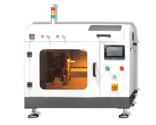
Ultrasonic spray fuel cell catalyst coating system can produce highly uniform, repeatable and durable coatings. Our ultrasonic spraying can well control coating properties, significantly reduce material usage, and reduce maintenance and downtime.
Our company’s ultrasonic spraying equipment can be sprayed on a variety of different metal alloys, including the preparation of platinum, nickel, iridium and ruthenium-based fuel cell catalyst coatings, as well as PEMs, GDLs, DMFCs (direct methanol fuel cells) and SOFCs (solid Oxide fuel cell) manufacturing. The battery manufactured by this technology has the characteristics of high battery load and high battery efficiency.
The optional ultrasonic dispersion system can uniformly disperse the catalyst solution without blocking the ultrasonic nozzle, thereby providing a uniform and homogeneous fuel cell catalyst coating, and has a controlled droplet size from ultra-low flow to production-scale flow.
