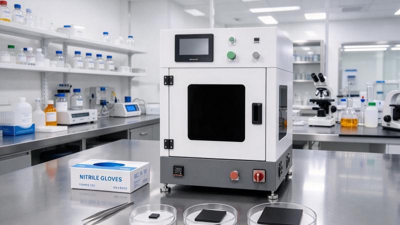
Iridium Oxide Catalyst Deposition by Ultrasonic Spray: Single-Sided CCM Coating at 2 mg/cm²
A Defined Single-Sided CCM Coating Task
Proton exchange membrane water electrolysis uses catalyst-coated membrane (CCM) structures in which the oxygen-evolution side may incorporate iridium-based catalysts. Iridium oxide (IrO₂) is a material of interest for the anode catalyst layer because of its activity and stability considerations in acidic oxygen-evolution environments. In practice, electrode durability and performance depend on catalyst grade, ionomer, membrane, operating conditions, and layer architecture.
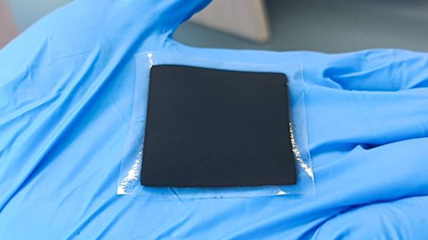
Consider a specific development task: a 7 × 7 cm membrane, a centered 5 × 5 cm anode coating window, and a nominal IrO₂ catalyst loading of 2 mg/cm² on one side only. This geometry gives a 49 cm² membrane and a 25 cm² coated area. It is important not to confuse the membrane area with the active coating area when calculating material requirements.
The mass balance for the requested geometry
Theoretical IrO₂ mass in the specified coated region is 25 cm² × 2 mg/cm² = 50 mg of dry IrO₂. This is the target deposited catalyst mass, not necessarily the total dry ink mass. If the formulation includes ionomer or other nonvolatile components, the complete dry layer will weigh more than 50 mg. The amount of ink dispensed must also account for measured deposition efficiency and the catalyst mass fraction of the liquid ink.
For example, a formulation worksheet should list the actual IrO₂ mass fraction, total nonvolatile fraction, target coated area, expected transfer efficiency, and planned number of passes. No specific solvent volume or pump rate can be responsibly prescribed without those inputs. A mass-balance calculation should be verified with experimental coating results.
Why Ultrasonic Spraying Is Considered for IrO₂ Catalyst Layers
Metered atomization and patterned coating
An ultrasonic spray system atomizes a liquid dispersion through vibration at the nozzle tip and can use controlled gas flow to shape the spray. A programmable stage moves the plume over the target area. For a rectangular CCM window, a defined raster pattern can help manage line overlap, edge coverage, and repeatability. The actual spray footprint must be characterized with the chosen ink and nozzle.
IrO₂ catalyst particles may settle or agglomerate, and catalyst-containing dispersions can exhibit formulation-dependent viscosity. Stable mixing and controlled delivery are therefore central to a consistent coating. If a formulation uses ionomer, the ionomer-to-catalyst ratio affects layer cohesion, transport pathways, and electrochemical behavior. Ultrasonic atomization alone does not resolve an unstable ink.
One-sided coating without contaminating the reverse face
The membrane should be secured on a clean support that protects the reverse face and allows controlled removal after coating. A suitable mask or precisely programmed spray boundary may define the 5 × 5 cm region. Edge overspray and the plume’s finite width must be considered; a nominal 5 cm travel path does not automatically produce a sharply bounded 5 cm deposit.
A low-distortion holding strategy is especially important for thin polymer membranes. Excessive vacuum, thermal gradients, or solvent exposure may introduce wrinkles or local changes in membrane dimensions. Verify that the fixture can support the 7 × 7 cm sheet while leaving the desired 5 × 5 cm coating window accessible.
Developing the Spray and Drying Sequence
Start with substrate and ink qualification
Record the membrane identity, thickness, conditioning method, and allowable temperature. Separately, record the IrO₂ powder grade, particle dispersion behavior, solvent blend, ionomer identity, and total solids. Conduct a compatibility test on sacrificial membrane samples before using the full coating recipe.
An initial feasibility trial should establish whether the dispersion atomizes consistently and whether deposited droplets wet the membrane without excessive beading or flooding. Inspect for clogging, catalyst accumulation at the nozzle, and any visible agglomerates. Maintain safe controls for any flammable or otherwise hazardous solvents used in the formulation.
Build the loading in multiple controlled passes
Rather than targeting the full 2 mg/cm² in a single wet application, a multi-pass strategy can reduce local liquid accumulation. Between passes, allow sufficient solvent removal while avoiding excessive temperature or prolonged drying that may damage the membrane. Pass count and deposition intensity should be chosen from measured mass gain and observed layer quality, not from an unverified universal recipe.
Track deposited catalyst loading as the process develops. A coating that is too wet may redistribute solids during drying; a coating that is too dry may show poor particle consolidation or insufficient adhesion. Both conditions can compromise layer uniformity. Cross-sectional imaging and surface inspection can help distinguish these outcomes.
Verifying the 2 mg/cm² Anode Coating
Geometric and gravimetric checks
Measure the actual coated boundary and confirm that the reverse face remains free of unintended deposition. A dry mass gain may provide a useful first check when membrane conditioning and other solid constituents are controlled. Because the intended IrO₂ mass is only 50 mg, weighing methods must have adequate resolution and account for changes in membrane moisture content.
If the dry layer contains binder, a simple total mass difference cannot by itself confirm the exact IrO₂ loading. Depending on available laboratory methods, catalyst-specific analysis or calibrated mass balance may be required. Sample multiple positions within the 25 cm² region to investigate edge-to-center variation.
Morphology, adhesion, and functional evaluation
Inspect the film for cracking, bare spots, edge ridges, and particle agglomeration. Evaluate adhesion using a method appropriate for the delicate membrane and catalyst layer. Subsequent CCM assembly and electrochemical testing should be planned by the device developer, with results interpreted against the complete cell design rather than spray appearance alone.
For iridium-containing systems, catalyst conservation is economically important. Overspray recovery, transfer efficiency, and cleaning losses should be measured, but no recovery rate should be assumed without test data. A well-designed process trial can identify where catalyst is being lost and whether the coating geometry can be improved.
From a 7 × 7 cm Trial to a Repeatable Process
The 7 × 7 cm membrane and 5 × 5 cm coating window provide a manageable development geometry. Document the membrane fixture, ink age, mixing conditions, spray pattern, drying intervals, environmental conditions, and final catalyst loading. Repeat the trial to determine whether the same result can be reproduced. Only then should higher throughput or a larger coating area be considered.
An ultrasonic spray system can support the investigation of single-sided CCM fabrication, but it does not by itself certify electrochemical performance, durability, or commercial readiness. Those outcomes require device-specific testing.
Plan an IrO₂ Catalyst Deposition Trial with Cheersonic
Cheersonic can discuss your single-sided CCM objective, including the 7 × 7 cm membrane, 5 × 5 cm anode region, and target IrO₂ loading of 2 mg/cm². Contact the team to review ink handling, masking, drying, and a practical sample-coating test plan. See ultrasonic coating equipment solutions and request a coating trial to evaluate your catalyst deposition project.