Catalyst Deposition on Proton Exchange Membranes
Catalyst Deposition on Proton Exchange Membranes: Ultrasonic Spraying of Water–Isopropanol Inks
Understanding Water–Isopropanol Catalyst Deposition on PEMs
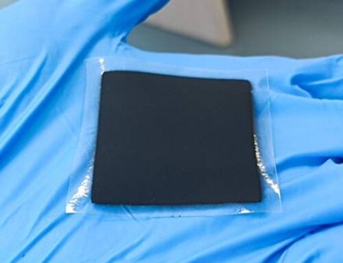
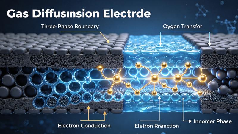
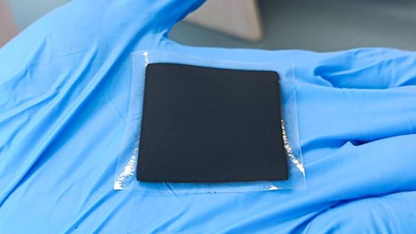
Catalyst deposition onto a proton exchange membrane (PEM) is a central manufacturing step for many catalyst-coated membrane (CCM) architectures used in electrochemical devices. An ultrasonic spray coating system can deliver an ink formulated with water and isopropanol (IPA) onto a membrane held on a controlled substrate fixture. The liquid mixture is a carrier for dispersed catalyst particles and, where appropriate, ionomer binder. Water and IPA are not themselves the catalyst. The composition of the complete ink, including solids, ionomer, and additives, determines whether a functional catalyst layer can be formed.
The challenge is not simply to produce a visible film. A useful CCM requires controlled catalyst mass, uniform coverage, appropriate porosity, intimate contact with the membrane, and a stable interface after drying. A process that looks uniform by eye may still have local loading variation, pinholes, agglomerates, or undesirable membrane swelling.
Why Mix Water and Isopropanol?
Wetting, evaporation, and ink stability
Water and IPA have different surface tensions and evaporation behaviors. Blending them can help tune how a catalyst ink wets a membrane and how deposited droplets dry. The optimum ratio is formulation-specific: it depends on the catalyst support, particle surface chemistry, ionomer type, membrane pretreatment, ambient humidity, and drying temperature. A solvent ratio that works for one formulation should not be transferred blindly to another.
Some PEM materials respond strongly to solvent and moisture exposure. Excessive wetting can cause temporary expansion, wrinkling, or loss of dimensional control, while rapid evaporation can create nonuniform solids redistribution. Before spraying, evaluate membrane compatibility using small coupons and compare dimensions before exposure, immediately after coating, and after conditioning.
Ink preparation before atomization
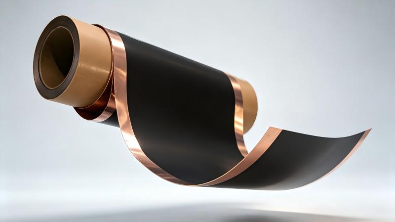
A reproducible preparation sequence begins with identifying the catalyst and ionomer specifications, recording the target solids concentration, and choosing a controlled dispersion method. Agitation, sonication, and filtration may be considered, but each can affect catalyst agglomerates or binder structure. Verify that the resulting dispersion remains stable over the intended production period. Document viscosity, solids fraction, particle-size behavior, and any sedimentation.
IPA is flammable. Ink preparation, pumping, spraying, and drying must be assessed for vapor accumulation, ventilation, ignition sources, solvent-compatible materials, and applicable workplace controls. A suitable enclosure and exhaust strategy are engineering requirements, not optional accessories.
How Ultrasonic Spray Coating Works
Fine droplet generation and controlled delivery
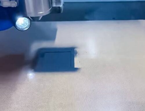
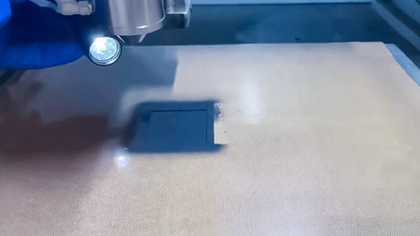
An ultrasonic nozzle uses high-frequency vibration to atomize a compatible liquid into droplets. A metering pump feeds the nozzle, and a low-pressure shaping gas can guide the plume toward the membrane. Relative to uncontrolled manual application, programmed motion and metered flow make it easier to define repeatable spray passes. They do not guarantee coating quality without ink and process optimization.
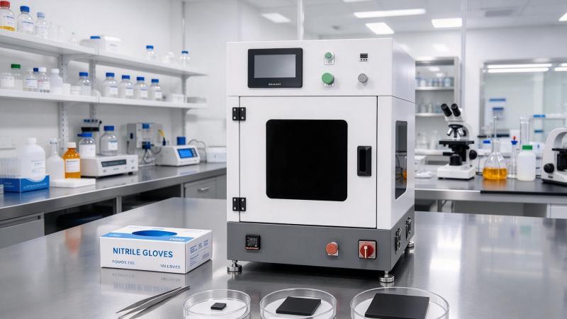
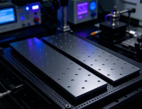
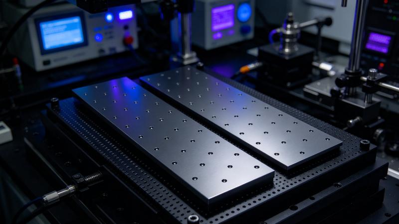
For membrane coating, the equipment configuration typically includes a liquid delivery module, ultrasonic spray head, motion stage, membrane support, controlled exhaust, and drying capability. A flat vacuum fixture may help restrain membrane movement, provided the vacuum pattern does not imprint or damage the substrate. Temperature should be selected with reference to membrane limits and the actual ink rather than assumed from another process.
Pass strategy and layer buildup
Multiple light passes are often easier to control than one wet, heavy pass. Each pass deposits a small fraction of the required solids; intermediate drying limits excessive liquid accumulation. Nozzle-to-substrate distance, travel speed, overlap, flow rate, and atomization setting interact. Changing one variable can alter both deposition efficiency and final microstructure, so process trials should use a documented test matrix.
A practical starting experiment can compare a few solvent ratios and two or three deposition intensities while keeping catalyst chemistry and target area constant. The objective is to find a stable spray pattern without flooding the membrane. These are experimental factors, not universal machine settings or guaranteed production windows.
Calculating Catalyst Loading Correctly
From active area to required solids
Catalyst loading is typically specified as dry catalyst mass per coated geometric area, often in mg/cm². If the target loading is L and the coated area is A, the required dry catalyst mass is m = L × A. For an ink containing catalyst and ionomer, distinguish total dry coating mass from the catalyst-only fraction. Confusing these values can substantially distort the intended loading.
The sprayed liquid volume is not equal to the liquid volume that remains on the membrane. Transfer efficiency depends on plume width, nozzle alignment, spray overshoot, fixture design, and operating conditions. Establish actual deposition efficiency experimentally using a mass balance, suitable witness coupons, or a validated analytical method.
Protecting the membrane during coating
The membrane may curl or change dimensions during solvent exposure and heating. Support the sheet consistently, avoid unnecessary handling between passes, and monitor its edges and corners. If a heated stage is used, confirm actual membrane surface temperature rather than relying only on the stage setpoint. Drying should remove the carrier solvent without causing unacceptable membrane deformation or catalyst-layer cracking.
Quality Checks for a Coated PEM
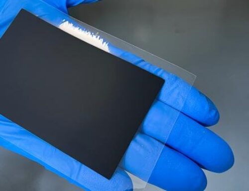
Useful checks include coated-area geometry, optical uniformity, dry mass loading, thickness or cross-sectional structure, adhesion, and defects. Depending on the device, electrochemical testing may assess whether the layer has the intended function. A uniform-looking spray film is not evidence of electrochemical performance. Results should be compared against a clearly defined acceptance plan and recorded with ink batch, nozzle settings, membrane batch, and environmental conditions.
For a process-development program, retain uncoated control membranes and at least one reference coating method when feasible. Compare drying shrinkage, catalyst utilization, and local uniformity across representative positions. Repeatability over several samples is more informative than one attractive demonstration coupon.
Moving from Trial Coating to Repeatable Production
Scale-up requires more than increasing spray time. Larger coating areas change overspray, drying dynamics, stage movement, and solvent management. A production-oriented system should be assessed for pump stability, cleaning procedures, ink recirculation or mixing, exhaust handling, fixture repeatability, and in-process inspection. The goal is to establish a robust relationship between delivered ink, deposited catalyst mass, and acceptable membrane condition.
Ultrasonic spray coating is therefore a process platform for investigating catalyst deposition on PEMs, not a substitute for material qualification. Membrane chemistry, catalyst formulation, coating sequence, and downstream assembly must be validated together.
Discuss Your Catalyst Deposition Project with Cheersonic
If you are developing a water–IPA catalyst ink for direct PEM coating, contact Cheersonic to review your membrane size, solvent system, catalyst loading target, and handling constraints. A small-scale coating sample test can help assess wetting, uniformity, and process feasibility before equipment decisions are made. Explore Cheersonic ultrasonic coating equipment solutions and ask about arranging a coating trial for your catalyst deposition project.